The JMB Series is the most powerful and feature rich electric fence energizer JVA has made to date. This continues JVA’s push for technical superiority in the area of Monitored Electric Fencing and IP Energizers(R). While the JMB was specifically designed for Game Parks and Exclusion Fencing, they are also well suited to any large permanent electric fence. The highest powered JMB produces a stunning 46J of stored energy. At this time the JMB series consists of 6 models:
JMB32-ZM1
JMB32-ZM2
JMB32-ZM50
JMB25-ZM1
JMB25-ZM2
JMB25-ZM50
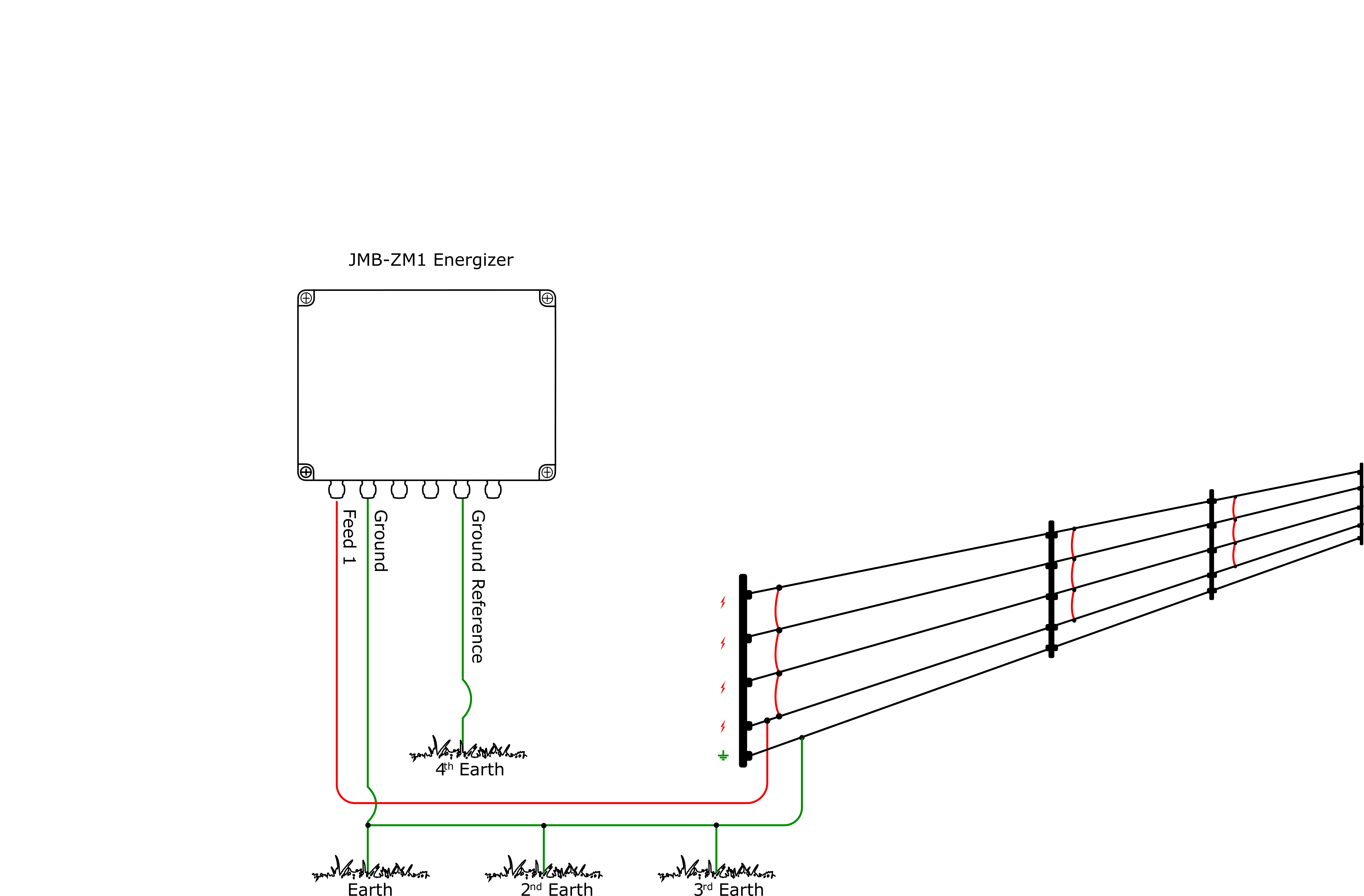
The ZM1 is a single zone energizer designed for large complex fences.
Four of the six internal fence connection terminals are used for the ZM1 model. The Fence return and the Ground reference are optional.
| Energizer | Fence |
|---|---|
| Feed 1 | Start of fence 1 |
| Ground | Fence earth |
| Feed 2 | Not Used |
| Return 1 | (Optional) End of Fence 1 |
| Reference Ground | (Optional) Earth |
| Return 2 | Not Used |
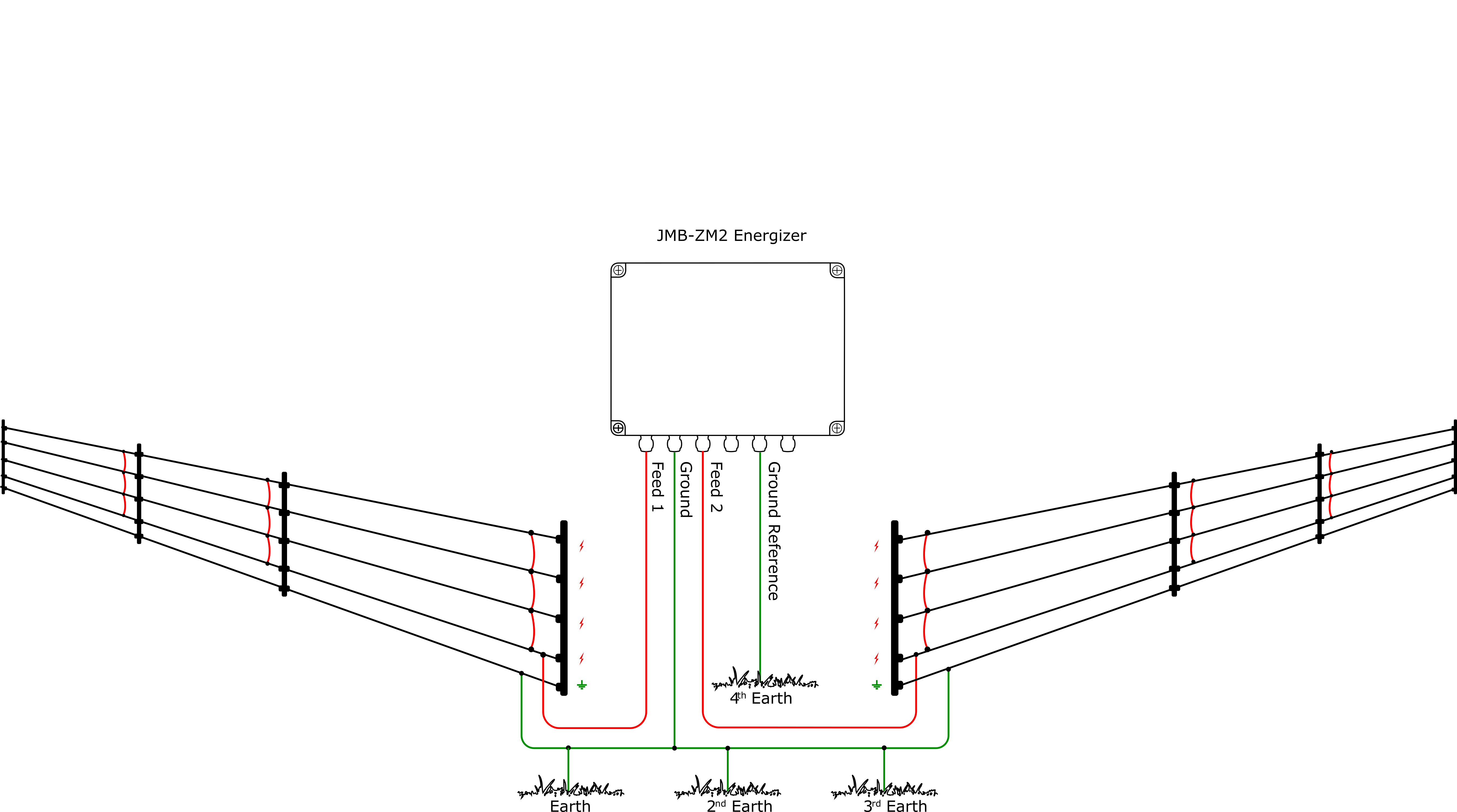
The ZM2 is a dual zone energizer. Designed for powering and monitoring two sections of a boundary fence.
All six internal fence connection terminals are used for the ZM2 model. The Fence returns and the Ground reference are optional.
| Energizer | Fence |
|---|---|
| Feed 1 | Start of fence 1 |
| Ground | Fence earth |
| Feed 2 | Start of fence 2 |
| Return 1 | (Optional) End of Fence 1 |
| Reference Ground | (Optional) Earth |
| Return 2 | (Optional) End of Fence 2 |
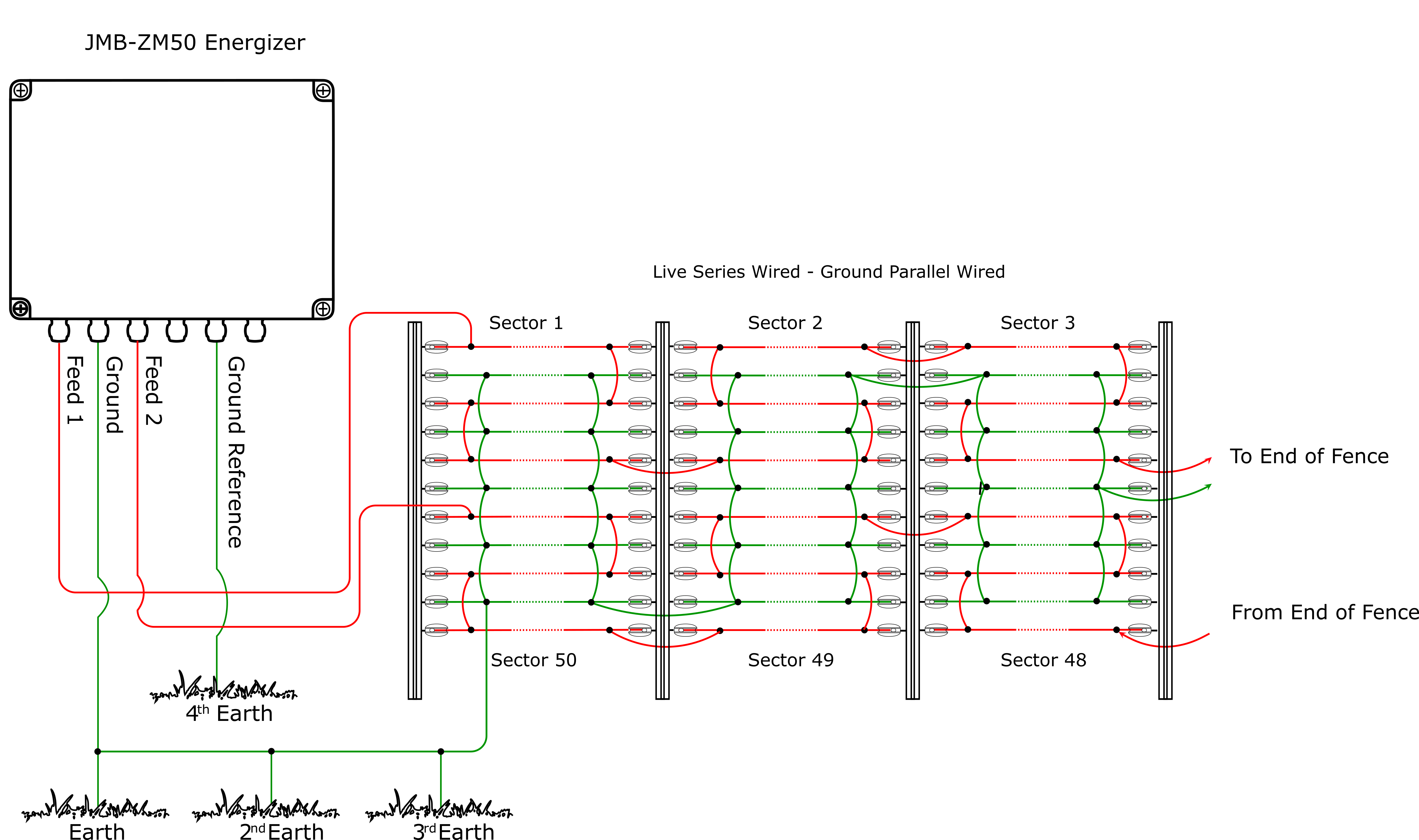
The ZM50 is a single zone energizer with loop monitoring. Designed for powering and monitoring a single boundary fence with the ability to detect and display a fault in one of up to 50 programmable sectors.
Four of the six internal fence connection terminals are used for the ZM50 model. The Ground reference is optional. If it is used, it should be connected to a separate earth stake.
| Energizer | Fence |
|---|---|
| Feed 1 | Start of fence live |
| Ground | Fence earth |
| Feed 2 | End of fence live |
| Return 1 | Not Used |
| Reference Ground | (Optional) Earth |
| Return 2 | Not Used |
Refer to user manual to program the sectors
Please read the entire manual before proceeding.
Design and build the fence. (Beyond the scope of this manual.) Ask your distributor for help if required.
Decide where the JMB is to be mounted. If on an external wall it should be housed within an equipment box and not in direct sunlight.
Mount the housing by using screws through the mounting holes in the corners of the box.
If you are using a 12V battery, connect the battery leads to the PCB terminals. Do not connect to the battery yet.
If you are using AC power, connect the power pack 24V to the PCB terminals. Do not turn AC on yet.
Wire the Fence and Earth cables to the fence terminals.
Put short pieces of wire into any unused cable glands to seal them.
While the Energizer is designed not to start when first powered up, make sure it is not going to hurt you if it does start up!
Connect the battery leads to the battery (if used).
Turn AC power to the 24Vdc power pack on (if used).
Power LED's will light up and the Wi-Fi LED will start blinking code 1 (1 flash each second).
Replace the front cover (lid).
Connect to the energizer using the virtual keypad (in the next section).
Arm (turn on) the JMB. The virtual keypad will now be able to show the fence voltage(s) and current(s).
Find and remove any faults on the fence.
Consult the main users manual for more information
The JMB Wi-Fi module can be used to configure and control the JMB. The Wi-Fi module defaults to Access Point (AP) Web server mode.
Before you start make sure the Wi-Fi status LED is blinking code 1.
Open the Wi-Fi settings on your phone and connect to the JMB's Wi-Fi.
The Name of the Wi-Fi (SSID) from your Energizer is JVA_Jumbo_xxxxxx where xxxxxx is the Serial Number of the unit. Select this SSID to connect to it.
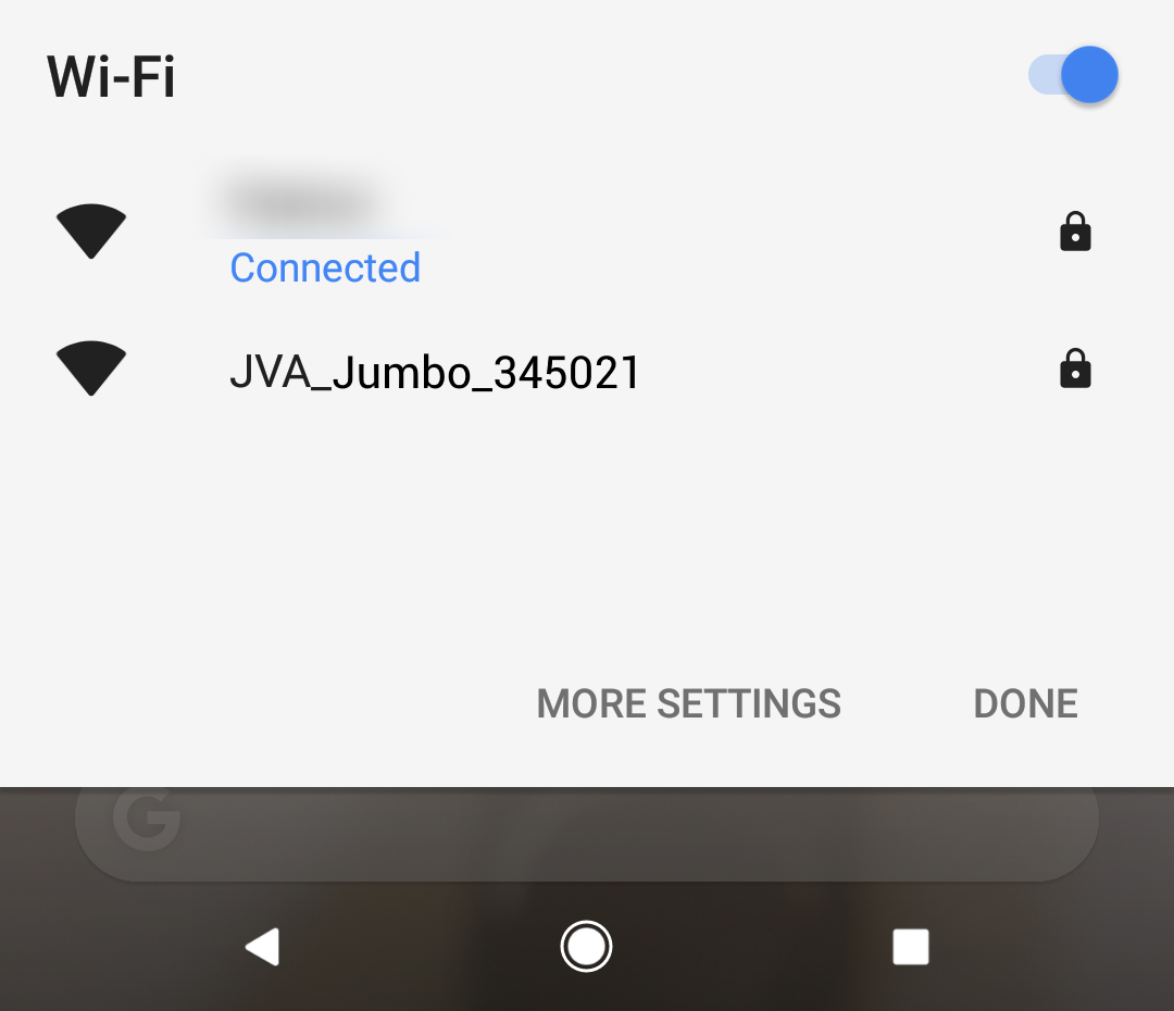
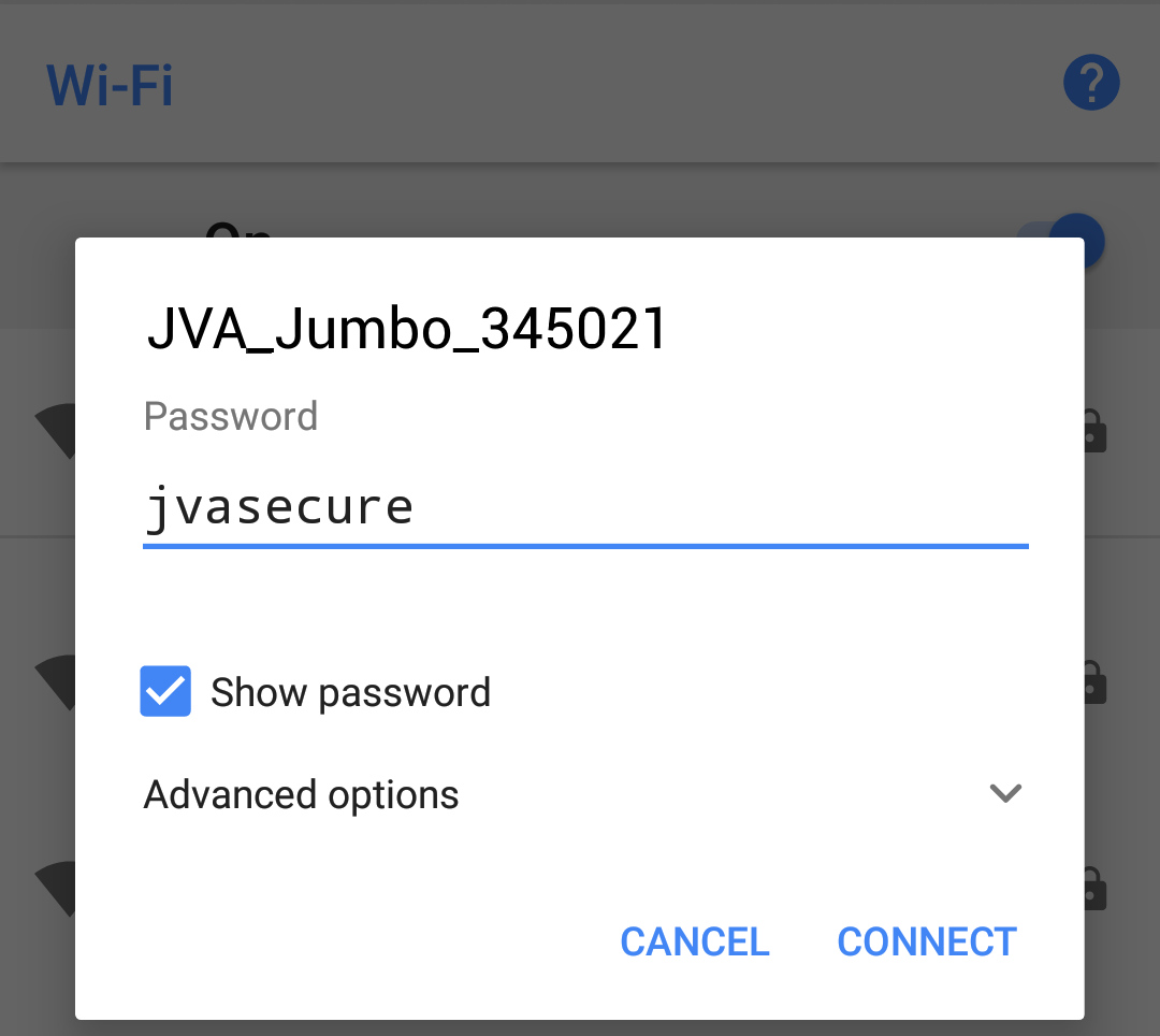
The connection is password protected.
The default password is: jvasecure
Enter the password and press CONNECT
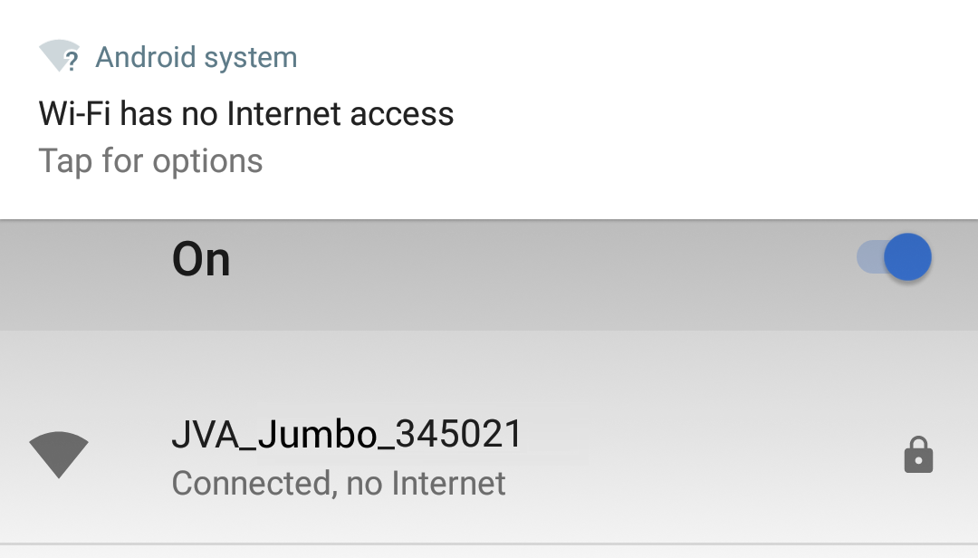
NOTE: Because this interface does not have an Internet connection, some phones will ask you if you want to remain connected. Click the tap for options if asked.
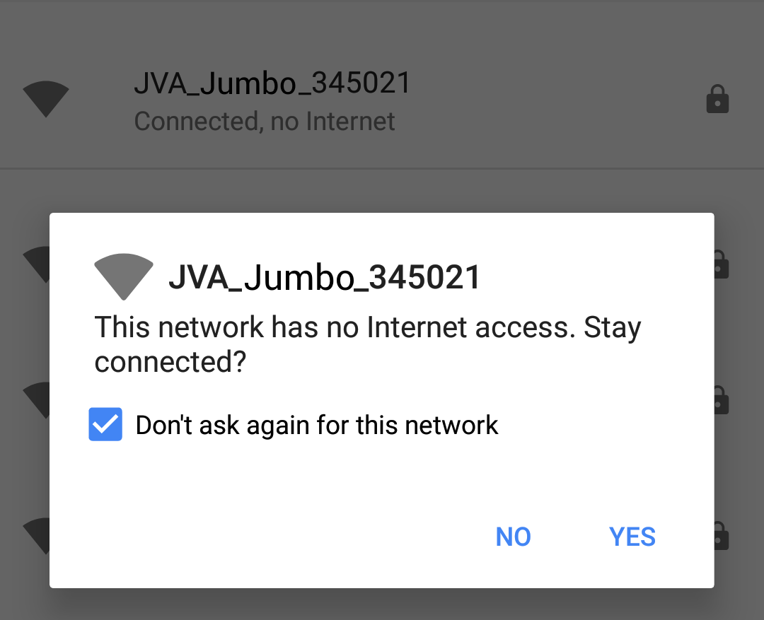
To ensure you can access the Web Interface, you need to answer YES to the “Stay connected?” questions. Tick the
box “Don’t ask again” if you will be connecting to this device more than once.
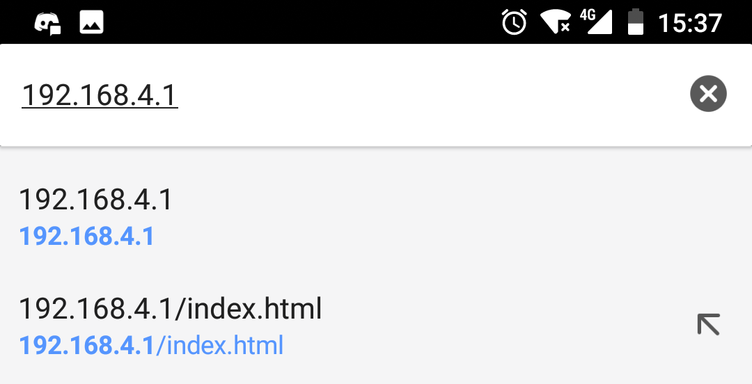
Open your browser (Chrome is preferred) and enter IP address 192.168.4.1 or you can use the following QR code.

This will open the Energizer screen which should be self explanatory. From here you can also access the Settings
Page.
| Failure | Probable cause | Solution |
|---|---|---|
| No lights on | Connected energizer is off
Power is not connected Power wires are reversed |
Connect power to energizer
Check your connection across the 12 Vdc and 12-24 Vdc inputs. Check to see that positive and negative wires are correct Check to see if your Battery is charged. |
| LED 'Wi-Fi' flashes once | Wi-Fi not connected | Connect to Wi-Fi access point. See the complete manual for more information |
| LED 'Status' flashes once | Tamper Alarm | Replace the enclosure lid or fit J12 to inhibit tamper |
| LED 'Status' flashes twice
|
24Vdc power fail | Restore power, check the main power fuse |
| LED 'Status' flashes three times | Low battery, bad battery | Charge or replace battery, check the battery fuse |
| LED 'Status' flashes four times | PCB service fault | Return to repair/service centre, more information is available via the Virtual Keypad. |
If you have questions or need further assistance, please email us at sales@jva-fence.com.au or call:
| Region | Number |
|---|---|
| Australia | 07 3103 0582 |
| South Africa | 0861 782 349 |
| USA | 512 466 1859 |
| World Wide | +61 7 3103 0582 |
For more information on the JMB Series Energizers, consult the main manual.